Use the Rotate Point Symbols tool to rotate point symbols or align them with nearby line features.
For our example in the procedure below, we have a layer that displays outdoor lights. Each light is represented by an arrow point feature. To visualize the data, we use the Rotate Point Symbol tool to rotate each arrow symbol to represent the direction each light faces.
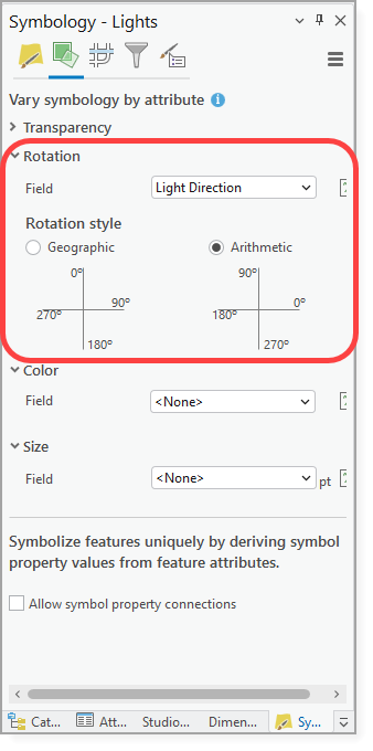
Before you begin, you must have a rotation field defined in the point layer's symbology, as shown in the figure below. See Esri's Vary Symbology by Rotation for more information.
To rotate a point symbol:
1.Ensure that a rotation field is defined in the point layer's symbology.
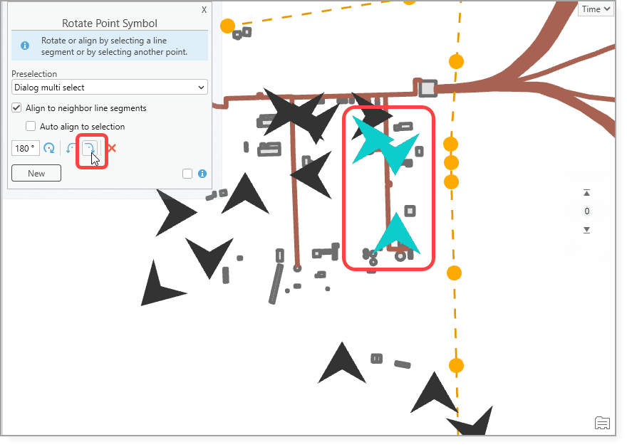
2.Go to Studio Toolkit > Edit > Rotate Point Symbol to open the Rotate Point Symbol window.
3.Use the Preselection options to select at least one point on the map to rotate or align.
You can expand the point selection at any time. For example, if a rectangular map selection includes at least one point symbol that is not part of the current edit session, it is added to the point selection. All other geometry types in the selection (such as lines) are ignored.
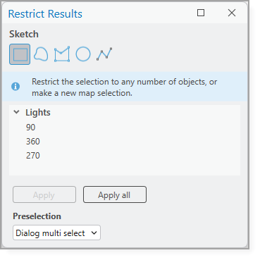
For our example, we use the Dialog multi select option. We select our three points on the map, which automatically opens the Restrict Results window, and click Apply All.
The Restrict Results window only appears if you use the Dialog multi select option.
The selected points are highlighted on the map.
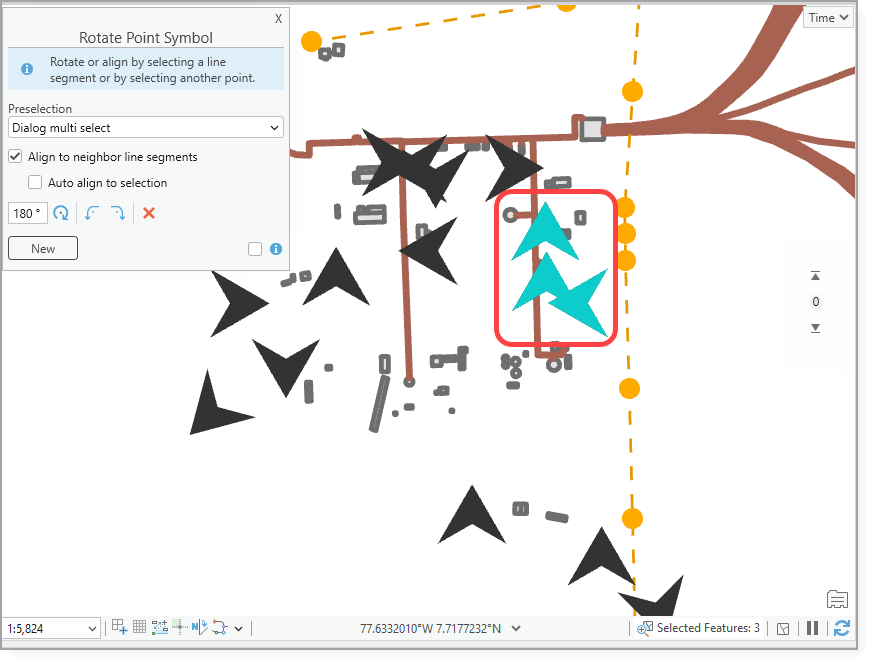
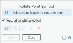
4.Use the functions in the Rotate Point Symbol window to rotate the symbols as necessary. We use Rotate Right to rotate the symbols 90 degrees.
5.Close the Rotate Point Symbol window when you are done.
Function |
Description |
Keyboard Shortcut |
|---|---|---|
Specifies how you can select a point before applying the rotation. •None: No preselection. •Dialog single select: Select one point on the map then adjust the rotation in the Rotate Point Symbol window. •Dialog multi select: Select at least one point on the map to open the Restrict Results window. Use the Sketch tools to draw an area on the map to limit the selection to specific objects or make a new map selection. |
N/A |
|
Align to Neighbor Line Segments* |
If enabled, the tool attempts to identify line segments underneath each point location. •If a single line segment is found, the point symbol aligns to that line. •If the point is a vertex of a polygon, the point symbol aligns based on the angle difference. Both polyline and polygon segments are supported. If disabled, line segments are not detected automatically. After selecting point features, you must manually identify the line or lines on the map to which the symbols should be aligned. To select multiple lines, hold the Shift key. |
N/A |
Auto Align to Selection* |
If enabled, When enabled, the tool automatically attempts to identify line segments related to the selected point locations. •If a single line segment is found, the point symbol aligns to that line. • If the point is a vertex of a polygon, it is aligned based on the angle difference. Both polyline and polygon segments are considered. If disabled, you must manually select the lines on the map to align the points. To select multiple points, hold the Shift key. |
N/A |
|
Specifies the rotation angle for all selected points. |
N/A |
|
Rotates by the set angle. |
N/A |
|
Rotates 90° to the left. |
Ctrl + Left |
|
Rotates 90° to the right. |
Ctrl + Right |
|
Resets the symbol rotation to 0. |
Esc |
New |
Clears the current selection to allow a new point selection. |
N/A |
Info |
When selected, a dialog shows additional help about the process. |
N/A |
*All alignment calculations use individual line segments, including those from polygons or merged geometries. |
||


