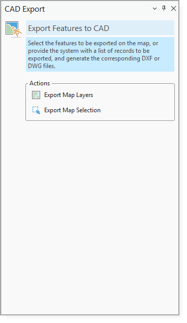
The CAD Export tool exports the current map selection or selected map layers to new or existing CAD files.
The tool creates or appends to existing .dwg, .dxf, or .dgn files.
The geometry, feature attributes, and coordinate system of ArcGIS feature layers are included when exporting to AutoCAD .dwg or .dxf files. The GIS data can be used with the ArcGIS for AutoCAD plug-in. Without the plug-in, the output geometry can be accessed as CAD entities.
You can use CAD Export to:
•export selected features from the current map to a CAD file.
•export features from selected map layers.
•create a new CAD file or append entities to an existing file.
•configure the output format, file, seed file, attributes, and symbology.
The table below describes the limitations that currently apply when exporting CAD files.
CAD Export Current Limitations
Limitation |
Description |
|---|---|
Point symbol scaling and rotation |
Point symbols with polygon geometries are exported based on their CIM symbology. However, their appearance in the CAD output may not exactly match their appearance in ArcGIS Pro. Individual symbol rotation and scale-dependent sizing, such as that used for protective pipes, may not be reproduced accurately. |
Dimensions |
Dimension features may not be completely represented in the exported CAD file because not all dimension information is captured during the Esri export process. |
Font-based symbol representations |
Custom fonts used to represent point symbols are not automatically transferred to or used by the CAD application. As a result, symbols that rely on custom fonts may not be displayed as expected in the exported CAD file. |
Overlaps and cutouts |
The export process does not resolve overlaps between CAD elements. For example, if CIM symbology causes a protective pipe polyline to appear wider in the CAD output, nearby text or annotations exported from the GIS may overlap with or be obscured by the line. |
Dashed lines |
Dashed lines defined using CIM symbology may not always be represented correctly in the exported CAD file. In some cases, a dashed line may appear as a solid line. |
To access the CAD Export tool:
1.Select CAD Export in the Data Transfer group on the Studio Toolkit ribbon.
Alternatively, you can select features in the Results List and select CAD Export from the Results List toolbar. The CAD Export panel opens, showing the selected records to export.
The CAD Export panel opens with the following options: