To export the map selection to a CAD file:
1.Open the CAD Export tool from the Studio Toolkit ribbon.
2.Click Export Map Selection.
The Export Map Selection pane opens.
3.Select the features on the map that you want to export.
The Selection area is populated with the selected features.
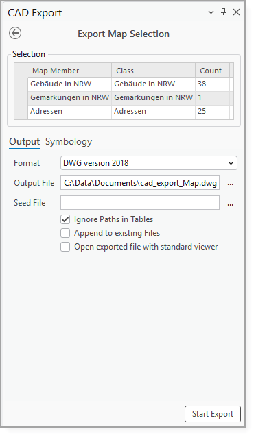
4.Configure the settings described in the table below.
Setting |
Description |
|---|---|
Output tab |
|
Format |
Configure the output format. The following formats are available: •Microstation DGN •DWG version 2018 •DWG version 2013 •DWG version 2010 •DWG version 2007 •DWG version 2005 •DWG version 2004 •DWG version 2000 •DWG version 14 •DXF version 2018 •DXF version 2013 •DXF version 2010 •DXF version 2007 •DXF version 2005 •DXF version 2004 •DXF version 2000 •DXF version 14 If you select Microstation DGN as the output format, CIM symbology from the corresponding layer is not evaluated. |
Output File |
Specify the path of the output CAD drawing file. The output path is overridden by valid file paths specified in an input feature field or field alias named DocPath, unless Ignore Paths in Tables is selected. |
Seed File |
Specify the existing CAD drawing whose contents and document and layer properties are used when creating the output CAD file. Seed files can be used to populate output CAD drawings with blocks, cells, layers, models, and layer symbology according to your CAD standards. The CAD platform and format version of the seed file overrides the selected output format. |
Ignore Paths in Tables |
When selected, valid paths are ignored and all entities are added to the file specified in the output file. This is the default. When cleared, each new CAD entity is written to the file specified by the DocPath field value. |
Append to Existing Files |
When selected, entities are appended to an existing output CAD file and the existing content is retained. When cleared, an existing output CAD file is overwritten. This is the default. |
Open Exported File with Standard Viewer |
When selected, opens the exported CAD file in the default application associated with the file type after the export is complete. |
Attributes tab |
|
Available/Exported Properties |
Define the properties for each class that will be exported. This option is only available if a list of dedicated records is exported. If a complete map selection is exported, this tab is unavailable. |
Symbology tab |
|
Point Display Mode |
Controls how point objects are displayed in the exported CAD drawing. This setting corresponds to the PDMODE system variable. |
Point Display Size |
Controls the display size of point objects in the exported CAD drawing. This setting corresponds to the PDSIZE system variable. A value of 0 displays points at 5% of the screen size. Positive values specify an absolute point size. |
Line Type Scale |
Controls the scale used to display line types in the exported CAD drawing. |
Skip CIM Symbology Evaluation |
Specifies whether to skip the evaluation of CIM symbology when exporting features. When cleared, CIM symbology from the corresponding feature is used to determine the display of points and polygons. |
5.Click Start Export.
The selected map layers are exported to a CAD file and saved to the specified file location.