Markup Module
The Markup Module implements the ability for end users to add markup text and shapes to the map. Markup is added to the map's drawing layer. The drawing layer does not appear in the layer list.
Markup exists only for the duration of the session—when the user closes the viewer, the markup disappears. To save markup across sessions and share it with other users, a signed-in user can save a project, provided the viewer supports projects. For information about projects, see Project Module.
The Markup Module is integrated with the Measurement Module. For more information on how measurements affect this module, see the section Markup Measurement.
Drawing creation tools and editing tools in the Desktop and Tablet interfaces
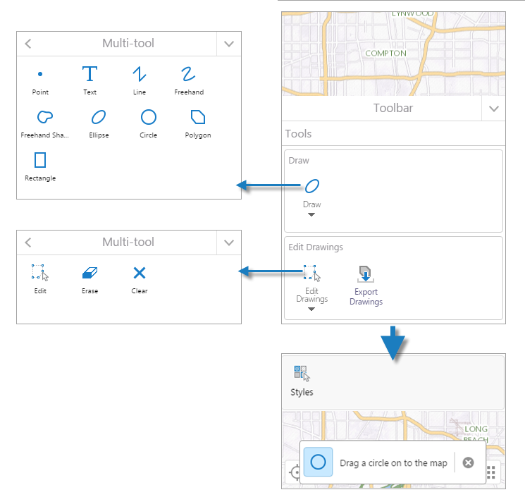
Drawing creation tools and editing tools in the Handheld interfaces
Text markup limitation:
The styling options for the halo (outline) effect on text markup (color and width) are not available if the viewer is used with Internet Explorer 11. Text halo styling options are available in all other supported browsers. See Client Requirements for information about supported browsers and devices.
Edit Drawings on the Map
The capability to include and provide editing of drawings on a map tip is dependent on "enabled" set to true on the GraphicsLayerIdentifyProvider in the configuration of the Identify module. If enabled is set to false, the include and edit capability on a map tip is not available.
When a user adds a drawing to the map:
-
If the user clicks a feature overlaid by the drawing, the feature and the drawing are included in the map tip.
Depending on the zoom level , a pushpin identifies the feature's location on the map.
-
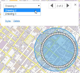
To edit the drawing included in the map tip, open the drop down list and select the drawing name to place it in edit mode. (Alternatively, click the next page or previous page arrows to go to the drawing page in the map tip.)
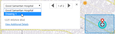
Select Drawing 1 to edit
Drawing 1 selected and in edit mode
-
-
If the user clicks a drawing that does not include another feature:
-
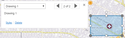
A map tip opens identifying the drawing.
-
The drawing is placed in edit mode.
-
Edit handles (not applicable to Points) are visible.
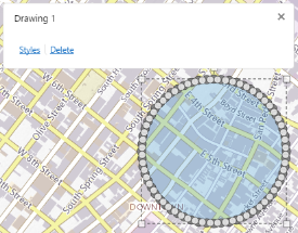
Map tip for Drawing 1 and its appearance in edit mode
-
When the drawing is in edit mode:
-
Depending on the type of drawing (point, text, circle, rectangle and so on), the user can edit text, add, delete or move vertices, relocate the drawing on the map, rotate it, and resize it.
-
The user can change the styles for the drawing by clicking Styles in the map tip to open the Select Drawing Style panel. See Markup Styles for more information.
-
The user can edit drawings that are overlaid on the map.
Each drawing can be selected in the map tip, either from the drop down list or by using the next page and previous page arrows.
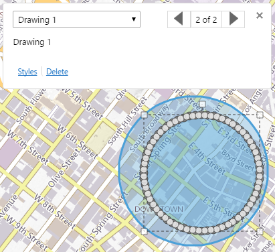
Drawing 1 in edit mode
Select Drawing 2 to edit
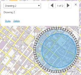
Drawing 2 selected and in edit mode
The user can also click a measurement drawing or a collaboration graphic to place it in edit mode. For more information, see Collaboration Module and Measurement Module.
Note that drawings, measurement drawings, and collaboration graphics are included in the results of an identify operation.
Editing Tools
Clicking a drawing to access the editing function via the map tip is preferable to using the Edit Drawings multitool in the toolbar.
Edit Drawings in the toolbar allows the user to edit, erase, or clear drawings. Note that using Erase on drawings that overlay each other erases all of the drawings. To avoid this behavior, the user can click one of the drawings to open the map tip, select the drawing to be deleted from the drop down list, and click Delete.
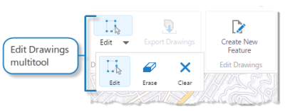
Edit tools for drawings in the Desktop and Tablet interfaces
Edit tools for drawings in the Handheld interfaces
Configure the Toolbar
The Markup Module provides tools for working with markup. These tools are not in the default toolbar—you must add them to the toolbar. If you use the Web GIS (Full )Toolbar, the markup tools are available in the Draw section on the Tools tab. For instructions on adding tools to the toolbar, see Toolbar.
The Markup Module makes the following tools available:
-
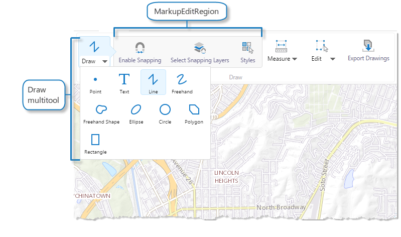
Draw (multitool): Drawing tools for various markup types.
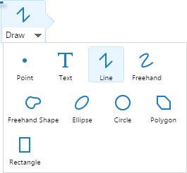
When the Draw multitool is selected, various markup tools become available
-
MarkupEditRegion: Select snapping rules and styles for new markup. For more information about the Styles tool, see Markup Styles.
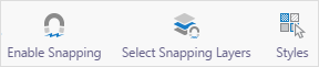
MarkupEditRegion tools, Enable Snapping, Select Snapping Layers, and Styles
-
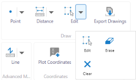
Edit Drawings (multitool): Tools to edit, erase, and clear drawings.
If the Edit tool is selected, the Erase and Clear tools can be activated. These tools apply to both drawings and measurements.
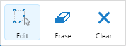
With the Edit tool activated, the Erase, and Clear tools become available
-
EditControlRegion: Edit snapping rules and styles for existing markup. For more information about the Styles tool, see Markup Styles.
MarkupEditRegion tools, Enable Snapping, Select Snapping Layers, and Styles.
-
Export Drawings: Export all drawings from the map to shapefiles. For more information, see Export Drawings.
Export Drawings tool
The Export Drawings feature can also be configured to the I Want To menu with the
ExportMarkupLayercommand.
The Drawing and Edit Drawing groups are included on the Web GIS (Full) Toolbar preset.
Markup Styles
When a user clicks a drawing to place it in edit mode, they can click Styles in the map tip to open the Select Drawing Style panel. Each type of drawing has a specific set of style options to choose from.
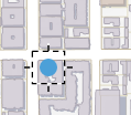
For example, to change from the default point style to an enlarged, angled image point style:
|
|
|
|
Default point style on a map |
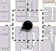
Image point style on a map |
-
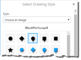
Click Styles in the map tip to open the Select Drawing Style panel.
-
Select Choose an image in the Type drop down list.
-
Click a black pin image.
-
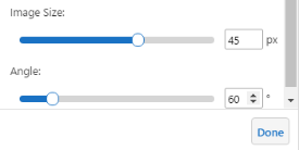
Change Image Size from 32 px to 45 px, and Angle from 0 degrees to 60 degrees.
-
Click Done to apply the style changes to the point image on the map.
The following image illustrates different markup drawings and their styles. You can edit the styles or add your own custom styles in the Module configuration.
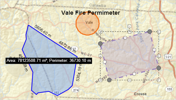
Different types and styles of markup
Measurement Markup
Markup made by the Measurement Module can be edited and styled like any other markup. If edited, measurements are recalculated and re-drawn on the map showing the new measurements.
You can move, resize and rotate lines, polygons and text markup. Points can only be moved. Text can be edited.
If several drawings overlay each other, click the top-most drawing to place it in edit mode and to open the map tip. In the map tip, select the drawing you want to edit from the drop-down list or use the next page or previous page arrows to go to the pages for the drawings.
Export Drawings
The Export Drawings tool extracts the markup layer and creates an Export.zip file containing all of the drawings. This feature is enabled only after markup has been added to the map in the viewer.
When the Edit Drawings tool is enabled, the Export Drawings tool is disabled. When the user selects the Export Drawings tool, a confirmation dialog box appears. Once accepted, the Export.zip file is saved to the user's device.
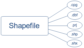
The shapefile format is a vector data format for GIS software developed by Esri. Shapefiles support point, line, and area features. A valid shapefile requires one .shp file as well as a .shx and .dbf file. For more information, see Esri's technical specification for shapefiles.
The Export.zip contains the user's drawings as shapefiles. Separate shapefiles are exported for each type of drawing. For example, if a map contained multiple point drawings and multiple polygon drawings, the export will contain a combined point.shp file and a combined polygon.shp file. Combined shapefiles can have the following names:
-
point.shp -
polygon.shp -
polyline.shp -
multipoint.shp
In addition to a .shp file, the exported shapefiles consist of a .cpg, .dbf, .prj, and a .shx. All five of these files are required.
Exported shapefiles do not include measurement markup, although the geometry values and scale will be preserved. Similarly, exports do not include text or drawing styles from the markup layer.
Copy to Drawing Layer
If a feature is selected and the panel displays its feature details, the user can use the Feature Actions Menu ![]() to access the Copy to Drawing Layer action. This copies the geometry of the selected feature to the drawing layer. You can then interact with a markup version of the feature in the same way that you would interact with and edit other markup on the map.
to access the Copy to Drawing Layer action. This copies the geometry of the selected feature to the drawing layer. You can then interact with a markup version of the feature in the same way that you would interact with and edit other markup on the map.
Commands
The Export Drawings feature can be configured to the I Want To menu with the ExportMarkupLayer command. For instructions, see I Want To Menu. The ExportMarkupLayer command calls the ExportGraphicsLayer command, which exports any markup in the form of extents, multipoints, points, polylines, and polygons.
Configuration Properties
Module
No configuration properties
Views
No views
View Models
-
MarkupViewModel:-
markupLayerName: The name of the layer on which drawings are placed. This layer does not appear in the layer list. The default name is Drawings. -
defaultPointMarkup: The default style of points. You can change the style of points in the viewer using the Styles tool.-
pointStyle: The default shape of points. Possible values include Circle, Diamond, Square. -
pointSize: The default diameter of points in pixels. -
pointColor: The default color of points in an ARGB hex string. All the colors in markup configuration use ARGB hex strings. For example, #6600FF00 would be green with 40% opacity.
-
-
defaultLineMarkup: The default style of lines. You can change the style of lines in the viewer using the Styles tool.-
lineStyle: The default style of lines. Possible values include: Solid, Dot, Dash, Dash Dot, Dash Dot Dot. -
lineWidth: The default width of lines in pixels. -
lineColor: The default color of lines in an ARGB hex string.
-
-
defaultPolygonMarkup: The default style of polygons. You can change the style of polygons in the viewer using the Styles tool.-
polygonBorderStyle: The default style of the border of polygons. Possible values include Solid, Dot, Dash, Dash Dot, Dash Dot Dot. -
polygonFillStyle: The default style of the fill of polygons. Possible values include Solid, Cross, Diagonal Cross, Forward Diagonal, Backward Diagonal, Horizontal, Vertical. -
polygonBorderWidth: The default width of the border of polygons in pixels. -
polygonFillColor: The default color of the fill of polygons in an ARGB hex string. -
polygonBorderColor: The default color of the border of polygons in an ARGB hex string
-
-
defaultTextMarkup: The default style of text markup. You can change the style of text in the viewer using the Styles tool.-
textStyle: The default style of text. Possible values include Normal, Italic, Oblique. -
textStyleWeight: The default weight of text. Possible values include Lighter, Normal, Bold, Bolder. -
textSize: The default size of text in points. For example, 14pt.The text size is expressed as a string, not as a number, so it must be surrounded by quotation marks.
-
textColor: The default color of text in an ARGB hex string. -
textFamily: The default font family to use for text markup. You can use any HTML font-family style attribute. For example, you can use specific font family names such as Arial and Segoe UI, or use generic types such as serif, sans-serif, cursive, fantasy, or monospace. Font family is expressed as a string.
-
-
customMarkupTools: If you create a custom tool that adds markup and you want the tool to work in the same way as the default tools, you must add the name of your custom tool to one of the four arrays in thecustomMarkupToolsobject.
For example, if you want your custom tool to be able to change the style of the markup in the viewer, you must add it to one of the arrays. If you add a custom tool to an array, for example a point array, and its style is changed in the viewer, it activates the point style picker so that you can change the style. The same is true for other styles:-
point: An array of strings containing the names of extra point markup tools. -
polyline: An array of strings containing the names of extra polyline markup tools. -
polygon: An array of strings containing the names of extra polygon markup tools. -
text: An array of strings containing the names of extra text markup tools
-
-
-
StyleSelectorViewModel:If you add a markup tool that is not part of the default tools, in order for the custom tool to work correctly, you must add the ID of the tool to one of the following arrays, depending on the type of markup your tool adds.-
customPointStyles: An array of custom point tools. -
customLineStyles: An array of custom line tools. -
customPolygonStyles: An array of custom polygon tools. -
customTextStyles: An array of custom text tools.
-
-
TransientMarkupPaletteViewModel: Noconfigurationproperties